Network Uplink Topology
Overview
Description
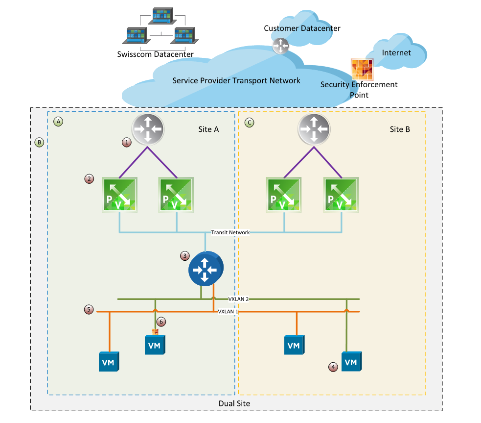
In order to provide connectivity to the outside world of the cloud, an uplink topology (UT) is deployed for each customer, i.e. tenant.
There is one option available
- The dual site UT configuration consists of four ESG's.
The described architecture is fully redundant. Per ESG, the available bandwidth is limited to 2 Gbit/s. Therefore, for a 4-ESG UT, 8 Gbit/s of bandwidth can be achieved per tenant. This limitation can be scaled up to 5 Gbit/s or 10 Gbit/s per ESG and a total of 20 Gbit/s or 40 Gbit/s per tenant. This total bandwidth can be achieved as aggregate traffic, not for a single flow.
A dynamic routing protocol is used to ensure updated routing tables. All ESG equally participate in the routing path with the use of ECMP, therefore traffic from one Datacenter can also exit in the other Datacenter per design. A preferred entry or exit path cannot be selected. The cloud outgoing network traffic is equally distributed over all available network paths.
Every UT is running in an isolated routing context which guarantees full separation of tenant network traffic. Every tenant communicates with his defined peers within a L3-VPN-tunnel and therefore fully isolated from other tenants. An additional layer of security for any communication endpoint is added by the distributed firewall (DFW) which is applied on any VM's network interface card (vNIC).